Useful design tips for SLM and MBJ metal 3D printing
Building a 3D printing component requires more than just additive thinking. There are a few tricks here and there, especially with metal. Now let our Exzellenc expert offer you some useful advices of design tips in metal 3D printing process.
While additive manufacturing may differ in many ways from other manufacturing processes, it shares the same difficulty in balancing design possibilities and performance requirements. because the manufacturing procedures used in 3D metal printing processes restrict design freedom. As a result, a component made utilizing several additive manufacturing technologies and having the same functioning requirements will always have a somewhat distinct appearance. This can already be evident in the simulation for a production-ready design, or there should be changes that are specific to the process. In this article we will show you the most crucial design advice for the two popular processes SLM and binder jetting.
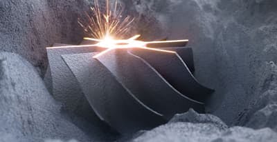
Building the SLM metal parts
The most well-known additive method for metal is undoubtedly selective laser melting (SLM, also known as LPBF or laser powderbed fusion). A squeegee is used to evenly spread metal powder onto a construction platform. A laser beam is then used to melt the metal at the predetermined locations. Thermal warpage and overhang are the method' two main drawbacks. Distortion happens as a result of unequal heat input. I have variable temperature distributions depending on how my component is constructed, explains Exzellenc expert. Additionally, it becomes extremely hot where a lot of material is melting. The geometry is affected by that. This thermal distortion can be avoided through procedure or design.
The component must be supported by support structures if it is positioned in the installation space at an angle that exceeds a specific threshold in the direction of assembly. Individual component structures and recesses also fall under this. The following metals, up to an angle of 30°, don't need supports, according to the British engineering company Crucible: stainless steel, titanium, and cobalt-chromium. Even at a 45° angle, inconel and aluminum could maintain themselves. In order to dissipate heat, support structures are required above a specified overhang angle.
Individual, free metal droplets are created when the laser strikes the bed of pure powder at the present build level without the melt being able to adhere to the component. These, in their most basic form, result in subpar surface quality, but they also pose a threat to the entire construction process. In addition to recyclable powder being wasted, the overhanging area's surface is at least rough and requires more intense reworking.
Design bores at SLM
Drilling is the following difficulty. They aren't actually round, at least not when viewed perpendicular to the direction of construction, claims Exzellenc expert. They ought to be created as a recess in the form of a drop. The drop transforms into a hole with the right tolerance by using the proper oversize and machine finishing. According to Crucible's design manual, holes up to 6 mm in diameter are not problematic. To prevent the geometry from collapsing, support structures must be placed in the center of holes with larger diameters.
There are two ways to join two geometric shapes together, such as two narrow, rod-shaped struts.
-
Either they join together strongly enough to support each other, in which case supports are not required.
-
You require supports if the place at which they touch is curved, such as to avoid a stress notch in the application.
The cost-effectiveness of a component is greatly increased by minimizing the number of support structures.
Construction for build-up welding
On the other hand, in the case of wire arc additive manufacturing (WAAM), or build-up welding with wire, the design should be without supporting structures. Using a robotic arm and the design data, a welding wire is melted and melted onto the construction board and the component in the WAAM process. Due to the process, all structures in the WAAM are very massive, including support structures, and necessitate extensive machining. Support requires time, both for printing and for post-processing. Two strategies exist for avoiding supporting structures:
- Prior to making any adjustments to the geometry, pay close attention to the build direction. At crucial moments, the process control reacts by changing the geometry or the welding current strength or build-up rate. Sometimes a strut can support itself with just a few degrees of outward or inward rotation.
- Gravity can be overcome with a WAAM system in which the construction platform has handling, and the structural challenge of working without support is made simpler. However, the build job's programming is where the complexity now lies.
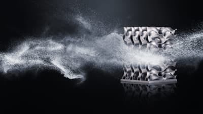
Building the Metal Binder Jetting parts
The good news is that metal binder jetting does not cause warping. Additionally, because the geometries are retained by the loose powder throughout the printing process, support structures are not required. Binder jetting is the process of joining metal powder with a binder to produce 3-dimensional components. The green portion needs to have this binder taken out once again. Either the binder is vaporized during a heat process that requires the now porous green body to be filled with another material, or the binder is dissolved during the sintering process, which causes the component to solidify right away. The green compact shrinks throughout any sintering process. The final shrinkage, or how much the component shrinks, is determined by how the component was designed and how much material was added where. Because more material shrinks more, distortion happens here.
The green compact is not only rejected because of uneven shrinkage. The material sinters to a very soft state. There is a chance that the structure will self-destruct and the component will collapse because of its own weight. According to Exzellenc expert, "in some processes, this can be resolved with ceramic support structures." The support structures for removal must also be accessible during design, usually by tapping or sandblasting.